
On a sloped land, the cutting plan (piece PCMI3 or DP3) is the document that contains the most reasons for refusal during the review process. The difficulty does not lie in the drawing itself, but in the consistency between the profile of the natural terrain, the projected volumes, and the elevation levels imposed by the PLU. We detail here the technical points that make the difference between an acceptable file and a request for additional documents.
Cutting axis on sloped land: choosing the layout that reveals the constraint
The choice of the cutting axis determines the readability of the project for the reviewer. On flat land, an axis perpendicular to the road is generally sufficient. On a sloped plot, this logic no longer applies.
We recommend tracing the cutting axis in the direction of the steepest slope, passing through the highest and lowest points of the built area. This layout highlights the maximum elevation differential between the natural terrain (TN) and the finished floor of the project. It is precisely this differential that the reviewer seeks to verify to control the actual height of the construction on the downstream side.
When the slope is oblique to the main facade, a second cutting axis perpendicular to the first allows for the display of lateral excavations and embankments. The PLU does not always require two cuts, but on a slope greater than a few percent, a single cut leaves shadow areas that the reviewing service will note.
The exact location of each axis must appear on the site plan (PCMI2), with clear markings (cut lines AA’, BB’). A file whose cutting plan for land and construction does not match the layout indicated on the site plan will be systematically returned for graphic inconsistency.
Elevation levels and natural terrain: errors that block the review process
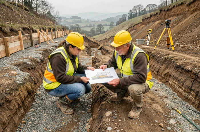
The profile of the natural terrain before work is the reference line from which everything is calculated: height at the ridge, height at the gutter, depth of foundations. On sloped land, this line is never horizontal, and this is where errors accumulate.
Natural terrain versus modified terrain
The TN is the profile of the ground before any human intervention related to the project. If the plot has already been excavated during a subdivision, the reference terrain is that observed at the time of submission, unless otherwise stated in the zoning regulations. Confusing TN with modified terrain distorts all declared heights.
We regularly observe cutting plans where the “before work” profile already includes the planned excavation platform. The reviewer compares this profile to the topographic survey or the contour lines of the cadastre. Any inconsistency triggers a request for additional documents, which prolongs the review period.
Minimum dimensions to be included
- NGF altitude (or relative levels) of the natural terrain at the ends of the cut and in front of each facade of the construction
- Altitude of the finished ground floor, ridge, and roof gutter
- Height of any retaining wall, measured from the finished ground on the downstream side
- Depth of excavations and thickness of embankments, with clear graphic distinction between the two
The PLU regulations specify the method for calculating height: from the TN at the midpoint of the facade, from the lowest point, or from the finished ground after work. The same building can be compliant or not depending on the calculation method used. Checking this point in the zoning regulations before dimensioning the cutting plan avoids costly revisions.
Water management and clay risk: what the cutting plan must anticipate
A sloped terrain concentrates runoff water downstream. The cutting plan must show how the project manages this flow; otherwise, the reviewer may require an additional hydraulic notice.
The elements to be graphically represented are the peripheral drains at the base of the buried wall, the collection pits, and the direction of rainwater flow towards the outlet (public network or ditch). On steeply sloped land, a ditch upstream of the construction protects the foundations by diverting surface runoff before it reaches the building.
Clay risk certificate and cutting plan
Since January 1, 2024, in areas with medium or high exposure to clay shrink-swell risk, a certificate acknowledging this risk must accompany the DAACT. The national exposure map was updated in January 2026, with legally applicable zoning since July 1, 2026.
This constraint has a direct impact on the cutting plan: the construction provisions (foundation anchoring depth, distance between plantings and the building, water management devices) must be consistent with the G2 soil study. A cutting plan that shows shallow foundations in clay areas will be contested during compliance checks, even if the permit has been granted.
Scale and software: producing a readable cutting plan on sloped land
The common scale for a cutting plan is 1/100 or 1/200. On sloped land, 1/100 is preferable: it allows for clear reading of height differences. Beyond 1/200, dimensions become difficult to verify visually.
Software such as QCAD or LibreCAD is sufficient to produce a compliant cutting plan, provided that work is based on a georeferenced topographic survey. A simple dimensioned plan made by a surveyor provides the necessary altitudes. 3D modeling tools (SketchUp, Archicad) can generate the cut directly from the model, but the final submitted file must remain a 2D dimensioned drawing, without realistic rendering or shadows.
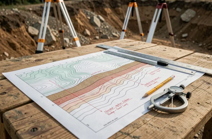
- Represent the TN with a thin continuous line and the profile after work with a thick continuous line
- Hatch the excavation and embankment areas with distinct patterns
- Indicate the property boundary and neighboring constructions if they are close to the boundary
- Add a legend if the plan contains more than three types of hatching or symbols
A technically correct cutting plan but graphically confusing remains a poor cutting plan. The reviewer has only a few minutes per file. The clarity of the drawing, the consistency of the dimensions with the site plan, and the faithful representation of the natural terrain are the three criteria that determine whether the file passes the first review or returns with a request for additional information.